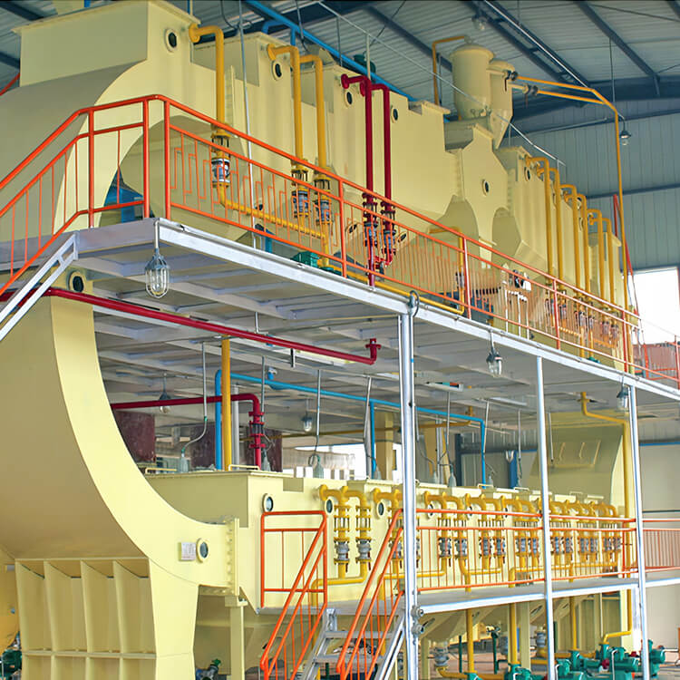
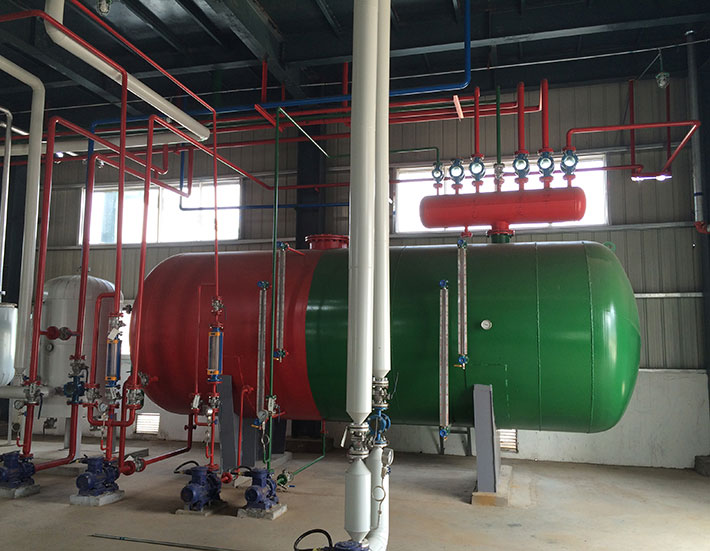
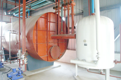
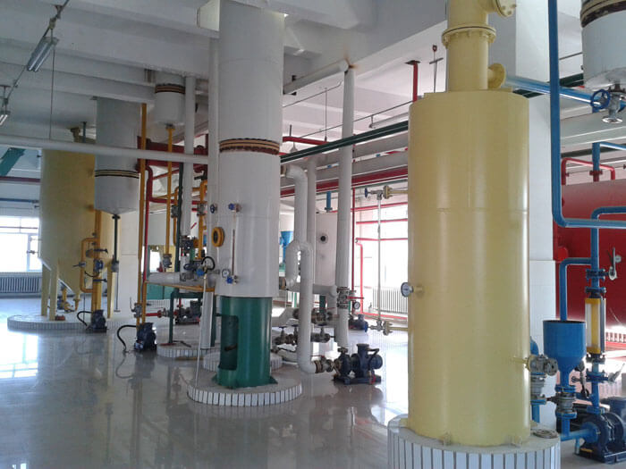
Solvent Recovery Systems in the Extraction Workshop
Solvent recovery systems consist of a condensing recovery system and a mineral oil system. The condensing solvent recovery equipment includes the condenser, solvent water separator, boiling tank, etc. We can equip the condenser according to your conditions. After condensing recovery, the vent gas still contains trace solvent which is recovered by the mineral oil system. The mineral oil system in the solvent recovery plant consists of an absorption column, desorption column, cooler, heater, heat exchanger, etc. Solvent recovery can decrease solvent consumption and improve production safety in the extraction workshop. Our solvent recovery equipment is easy to maintain and has a high solvent recovery rate.
Process of Condensing Recovery Systems in the Solvent Recovery Plant
- The solvent vapor from the first evaporator and second evaporator enters the evaporating condenser. The non-condensing vapor is pumped into the shell pass of the first evaporator. The condensate is pumped into the economizer and is heated by the non-condensing vapor from the shell pass of the first evaporator so that the temperature of the condensate from the economizer is increased and the temperature of the solvent from the water separator is increased.
- The mixed vapor from the stripping tower enters the stripping condenser. The condensate enters the water separator. The non-condensing vapor is pumped into the shell pass of the first evaporator.
- The mixed vapor from the desolventizer toaster enters the shell pass of the first separator. The condensate enters the water separator. The non-condensing vapor enters the economizer and is condensed by the condensate from the evaporating condenser. The condensate enters the water separator. The non-condensing vapor enters the desolventizing condenser. The condensate from the desolventizing condenser enters the water separator.
- The solvent vapor from the oil extractor enters the extracting condenser. The condensate enters the water separator.
- The solvent separated from the water separator flows into the solvent holding tank for circulation. The wastewater from the water separator flows into the boiling tank to be boiled with direct steam to strip the residual solvent. The solvent vapor enters the condenser. The waste water after boiled is discharged into the water seal tank.
- The solvent-carrying air from the desolventizing condenser, extracting condenser, water separator, miscellany tank, and solvent holding tank gathers in the balancing tank and then enters the vent gas condenser. The condensate enters the water separator. The vent gas enters the mineral oil system.
Process of Process of Mineral Oil System in the Solvent Recovery Plant
- The vent gas from the vent gas condenser enters the paraffin absorption column from the bottom and countercurrent contact with the cold lean oil flowing from the top when passing the stainless steel packing. The solvent vapor in the vent gas is absorbed by the cold lean oil, which then becomes the rich oil. The unabsorbed vent gas is drawn off through the vent gas fan at the top of the absorption column and vented into the atmosphere.
- The solvent-laden rich oil collected from the bottom of the absorption column is pumped by the rich oil pump into the heat exchanger and heated by the lean oil from the desorption column. After being heated to the required temperature by the paraffin heater, the rich oil enters the desorption column from the top and countercurrent contact with the direct steam injected from the bottom when passing the stainless steel packing. The solvent in the rich oil is stripped and the desorbed rich oil becomes lean oil and falls into the bottom of the desorption column.
- The lean oil is pumped by the lean oil pump into the heat exchanger to transfer heat to the rich oil. After being cooled to the ideal absorption temperature by the cooler, the lean oil enters the absorption column from the top for circulation. The mixed vapor discharged from the top of the desorption column enters the condenser. The condensate enters the water separator.
| Model(heat transfer area) |
Capacity |
| 1-2500m² |
50-6000t/d |